
The first step is to create the COG assembly language program to be loaded into our COG. For this example I used the Parallax Spin IDE to create the COG program. The COG program is created the same as any normal COG assembly object. The one difference is we will not be using any Spin language code at the start of the object. Since the Spin IDE requires at least one spinmethod before the DAT section containing the COG assembly language code we will include a stub function with no actual spin code. The following code snippet shows the start of the real time clock spin object source code.
CON
_clkmode = xtal1 + pll16x
_xinfreq = 5_000_000
PUB Start
''does nothing but must be there for spin IDE to compile

DAT
org 0
Entry mov TimeAdr, PAR
..............
Notice in the code snippet that the "Start" public method has no code to execute it is only there to satisfy the Parallax IDE.
For this example the source for the COG object can be found in the "Forth\Launch COG\clock.spin" file included with the MV4th demo version 0.91 and higher source files. To compile the COG object into a binary file load the clock.spin file in the IDE and select the "Run/Compile Current/View Info" menu selection or press the F8 function key. If your object compiles correctly the IDE will display the Object Info Dialog shown below. If the hex display is not showing in the Object Info Dialog, press the "Show Hex" button.
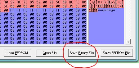
Press the "Save Binary" button and save the file to your computer. Make sure the saved file has the ".binary" file extension. We will need this file later so remember where you put it.
In order for MV4th to start the COG, MV4th will require access to a copy of the binary image to load into the COG. The only persistent storageMV4th has access to is the EEPROM based block device. Each MV4th block device block is 1k bytes in size. For this example we will store the binary image into device block index 31. Our binary COG test program uses less then 1k of space so it will fit in a single block. If your object binary is larger then ik bytes (256 longs) it will require 2 forth device blocks.
The ForthTerm program available in the MV4th16 dowloads will be used to upload the binary image to the forth block device. See the article Getting Started With MV4th16 for more information on using ForthTerm.
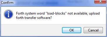
With ForthTerm connected to the MV4th system reset the propeller board and wait for the MV4th prompt to appear. In the ForthTerm programselect the "Upload Block File" commandunder the Communications main menu. In the displayed file select dialog select the "Binary File" option in the file extension selection,then slect the "clock.binary" file we created in the first step.ForthTerm will now display adialog that the Forth block load words are not loaded and offer to upload the code to the MV4th system, select "OK" to continue.
Once the code has been transfered to the MV4th system the ForthTerm program will display the "Transfer Blocks" dialog. Set the "First Block" setting to 31 then press the "Upload" button.

If no error is reported by the ForthTerm program you will have placed a copy of the COG binary image into block 31 of the MV4th block device.
The Forth source code for this exampleis provided in the text file "Forth\Launch COG\time.txt". This source code has also been saved tothe forth block file "Forth\Launch COG\time.blk" using the ForthTerm program. The real time clock Forth source code is comprised of two main parts; the first part of the code is used to set and read the real time clock, and the second part of the code is used to initialize and startthe COG running the real time clock.
The ForthTerm program can be used to upload the block file "Forth\Launch COG\time.blk" file in the same maner we loaded the COG binary image file above. When loading this example save the block file to block index 30 on the MV4th system. After the block file has been uploaded you can run the forth real time clock COG. To run the real time clock COG type "30 LOAD init-time" without the quotes and press enter. A prompt should indicate the COG index of the real time clock COG.
To set the time for the clock, type the following at the MV4th prompt; "$11223344. set-time" without the quotes and press enter. This will set the time to 11:22:33.44 (of course you would enter the correct time in 24 hour format). Do not forget the period at the end of the constant to indicate a double precision value.
To display the current time type "time" without the quotes and press enter.
Below is a copy of the provided source code for this example. We will examine the provided code section by section.
.( time demo, uses a COG to keep time, run init-time to start )
0 USER time-data 4 USER time-lock LOCK-NEW time-lock !
: t-lock BEGIN time-lock @ LOCK-SET WHILE REPEAT ;
: t-unlock time-lock @ LOCK-CLR DROP ;
: t. BASE @ >R HEX <# # # $2E HOLD # # $3A HOLD # # $3A HOLD
# # #> TYPE R> BASE ! ;
: time time-data Q@ t. ;
: set-time t-lock time-data Q! t-unlock ;
MARKER clock-code
31 CONSTANT cog-block 24 CONSTANT cog-offset
: qvar CREATE HERE 3 AND IF 2+ THEN ALLOT DOES> DUP 3 AND
IF 2+ THEN ;
1024 qvar cog-buffer
: init-time cog-block BLOCK cog-offset + cog-buffer 1024 MOVE
cog-buffer time-data COG-NEW ." Clock started on COG " . CR
BLK @ ?DUP IF BLOCK DROP THEN 2 MS clock-code ;
The first line of forth code will diplay a prompt when the code is loaded from the block device using the forth LOAD word.
.( time demo, uses a COG to keep time, run init-time to start )
The next line of source code is used to allocate two 4 byte variables in the MV4th user memory area. In MV4th the start of the user memory area is always quad byte aligned (long aligned). The first variable called "time-data" is used to hold the current time and the second variable called "time-lock" is used to hold the index of the propeller chip lock used to guard against two COGs changing the time value at the same time. Once the two variables are allocated the lock is allocated using the LOCK-NEW forth word and the returned lock index is saved into the second variable.The address of these variables will be past to the real time clock COG via the COG PAR register.
0 USER time-data 4 USER time-lock LOCK-NEW time-lock !
The next line of source code declares a forth word called "t-lock" to set the allocated propeller chip lock. The forth word loops setting the lock until the return value from the LOCK-SET forth word returns FALSE indicating the lock was clear before being set. See the parallax propeller reference guide for more information on using the propeller chip locks.
: t-lock BEGIN time-lock @ LOCK-SET WHILE REPEAT ;
The next line of source code declares a forth word called "t-unlock" toclear the allocated propeller chip lock. The "t-unlock" forth worduses theLOCK-CLR MV4thword to clear the lock. The LOCK-CLR forth word returns a value indicating the state of the lock before it was cleared. The DROP forth word removes this unwanted value from the forth data stack. See the parallax propeller reference guide for more information on using the propeller chip locks.
: t-unlock time-lock @ LOCK-CLR DROP ;
The next line of forth source code is used to create a forth word called "t."to display the time in human readable format. The code reads the time stored as 4 two digit packed BCD values and displays them placing a separator between the hours, minutes, second, and hundredths of a second values. The displayed time takes the form of HH:MM:SS.ss.
: t. BASE @ >R HEX <# # # $2E HOLD # # $3A HOLD # # $3A HOLD
# # #> TYPE R> BASE ! ;
The next line of forth code creates the forth word "time" that reads the current time from memory and displays the time at the console. The Q@ function is used to read a 32 bit COG long value and place it on the forth data stack as a double precision number.
: time time-data Q@ t. ;
The next line of source code is used to create the forth word "set-time" to set the time for the real time clock. The forth word first sets the propeller chip lock to guard the time value then sets the the new time value and finally clears the lock.
: set-time t-lock time-data Q! t-unlock ;
This is the end of the resident portion of the forth real time clock control code. The remaining lines of code are used to load the COG binary code and start the real time clock COG. This portion of the code starts with the forth word MARKER to allow us to free the memory used to load and start the code once the COG is started.
MARKER clock-code
The next line of forth source code creates two constants we need to load the COG with the binary image.The first constant called "cog-block" is used to hold the block index of the block that contains the COG binary image. The second constant called "cog-offset" is used to hold the byte offset from the start of the binary image to the start of the actual COG machine code. This is always 24 bytes when a spin object only includes a single spin method with no spin code or variables.
31 CONSTANT cog-block 24 CONSTANT cog-offset
In order to load the COG with the binary code we must copy the image from the forth block device to a quad byte aligned memory buffer. The buffer will require one or two kilobytes of memory depending on the size of the binary image. The copy buffer nust be quad byte (long) aligned for the COG to load an image from the buffer. In MV4th variables are word aligned not long aligned. The forth word "qvar" is used to allocate available that is always quad byte aligned. The next line of forth source code creates the "qvar" forth word.
: qvar CREATE HERE 3 AND IF 2+ THEN ALLOT DOES> DUP 3 ANDIF 2+ THEN ;
Next we need to allocate the COG image copy buffer. Since our example COG image is less the one kilobytes in size we only need to allocate a one kilobyte byte size variable. if the COG image is greater then 1K (is savedin more then one block) we would need a maximum copy buffer of 2K bytes. The maximum size of a COG image is 2048 - 64bytes. The last 16 longs in a COG are the special purpose registers and are not part of the COG binary image. The next line of forth source code allocates our copy buffer.
1024 qvar cog-buffer
The last lines of forth source code are responsible for allocating the copy buffer, loading the copy buffer with the COG binary image ans starting the real time clock COG. These lines of forth source create the forth word "init-time".
: init-time cog-block BLOCK cog-offset + cog-buffer 1024 MOVE
cog-buffer time-data COG-NEW ." Clock started on COG " . CR
BLK @ ?DUP IF BLOCK DROP THEN 2 MS clock-code ;
The first line of source code in "init-time" word copies the COG binary image from the stored block into the previously allocated copy buffer at the address returned by the "cog-buffer" variable. The copy starts at an offset of "cog-offset" (24 bytes) and continues to the end of the block. Next the COG is started using the COG-NEW forth word.
The address returned by the cog-buffer variable is the address of the image to load and the time-data word returns the address of our two long sized memory variables used to hold the current time and the index to the propeller chip lock. The remainder of the forth code displays a prompt to indicate the COG index of the real time clock COG.
The final line of code is used to restore the block buffer if we are loading from a forth block. Next we wait 2 mill-seconds for the COG to complete loading then call the forth word "clock-code" to free any memory we have allocated while loading the COG.
Last Updated on Wednesday, 28 July 2010 08:57